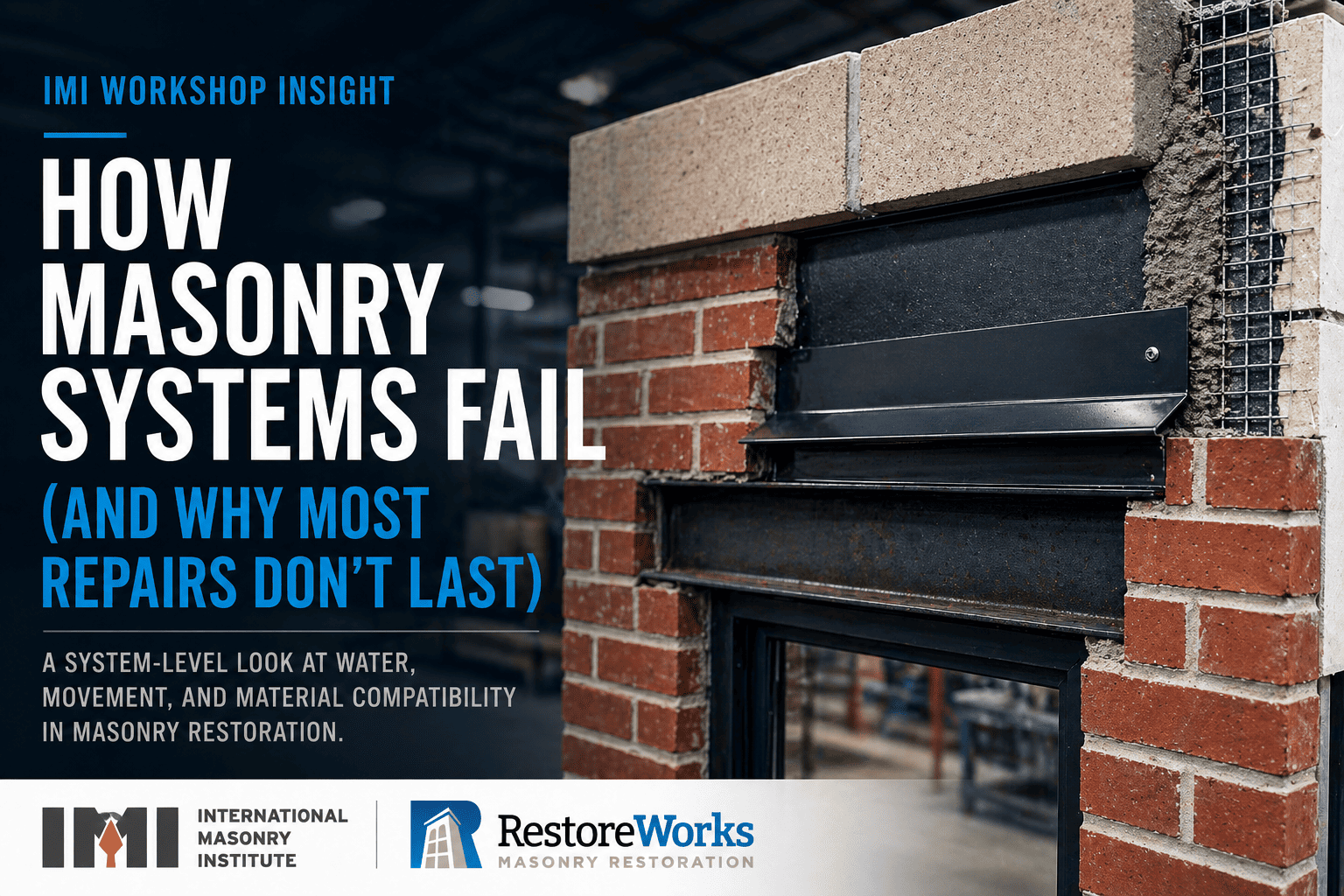
How Masonry Systems Fail (and Why Most Repairs Don’t Last)
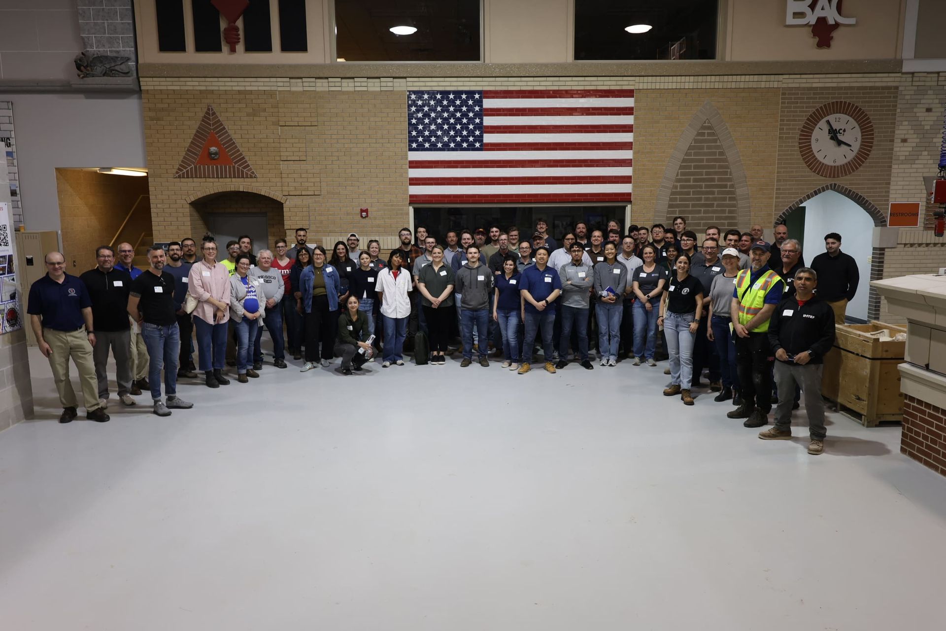
At a recent hands-on workshop hosted with the International Masonry Institute, we worked through four core areas of masonry restoration:
- Lintel Repair, Flashing & Bricklaying
- Mortar Extraction, Preparation & Pointing
- Anchoring, Stabilization, Stitching & Beaming
- Masonry Patching & Dutchman Repair
Each station focused on a different scope. But taken together, they reinforced a single reality:
Masonry failures are rarely isolated. They’re the result of systems breaking down.
Water enters the assembly. Materials don’t behave as intended. Movement isn’t accommodated. Repairs are made in isolation. And the cycle repeats.
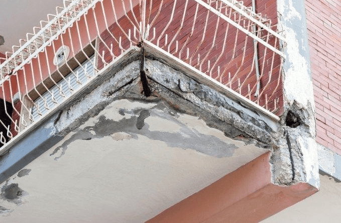
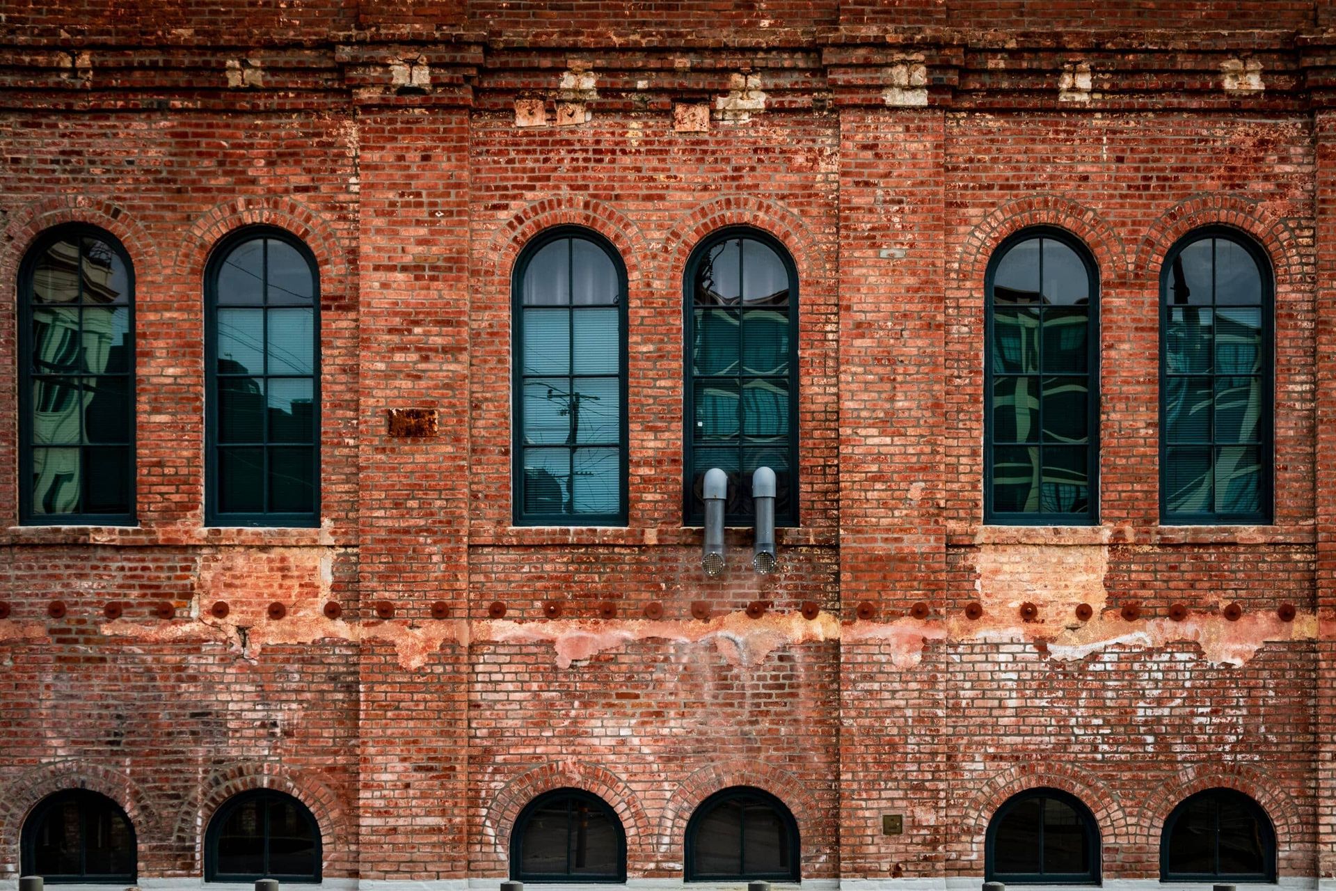
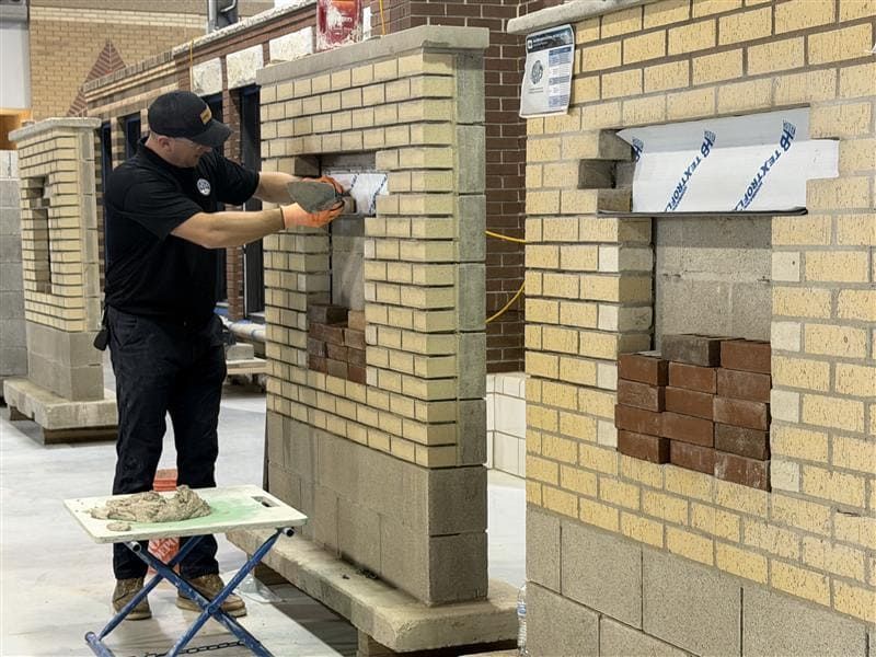
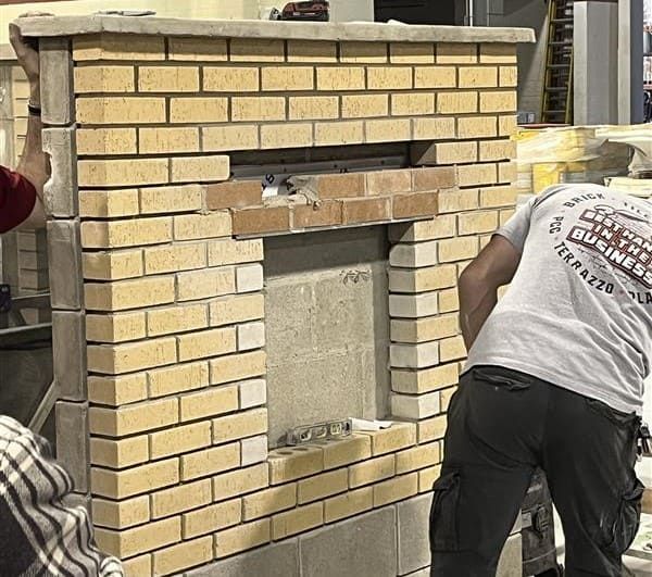
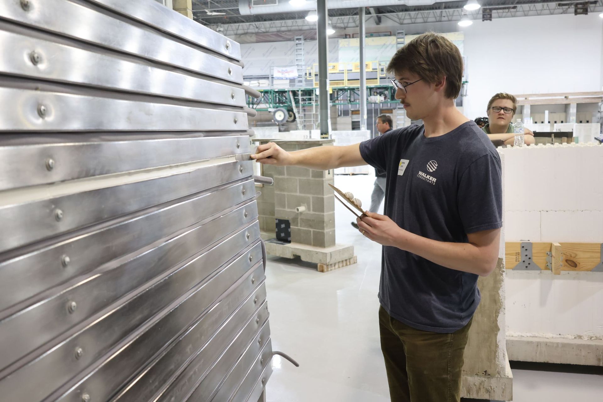
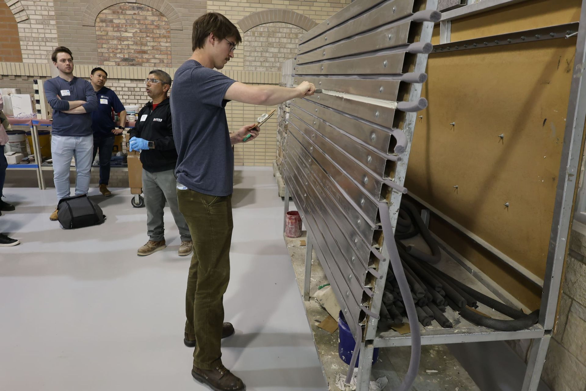
Station 1: Lintel Repair, Flashing & Bricklaying — Water Management Drives Everything
Water intrusion is not a defect in masonry, it’s an inherent condition.
Moisture enters through porous units, mortar joints, and microcracking, even when a wall appears intact. The function of the wall is not to eliminate water, but to capture, control, and discharge it before it causes damage.
At this station, the focus was on how that control happens at one of the most vulnerable transition points in the wall assembly: the lintel and flashing interface.
Why Flashing Is a System, Not a Component
Flashing is often treated as a single element. In reality, it is a coordinated drainage system made up of multiple components working together.
A properly functioning system includes:
- Steel lintels
- Cleaned and coated with corrosion-resistant material
- Installed with a slight positive slope to prevent inward drainage
- Continuous flashing
- Integrated with the backup system (either through-wall or terminated with a mechanically fastened bar)
- Installed to prevent water from migrating behind the assembly
- End dams and drip edges
- End dams to stop lateral water movement at terminations
- Stainless steel or copper drip edges to break surface tension and direct water outward
- Weeps and drainage components
- Mesh weeps that allow both drainage and airflow, supporting cavity drying
Material selection influences performance:
- Sheet metal flashing (stainless steel or copper) provides long-term durability
- Flexible composite membranes improve constructability but require proper sequencing and detailing
These components are not independent. They must be properly sequenced and integrated to function as a system.
Water Retention Is Where Failure Begins
When any part of the flashing system is missing, improperly installed, or treated as an afterthought, water is no longer controlled, it is retained within the wall.
That leads to predictable failure conditions:
- Steel lintels corrode and expand, causing rust jacking and displacement
- Saturated masonry undergoes freeze-thaw cycling, leading to cracking and spalling
- Moisture migration results in efflorescence and staining
- Embedded ties and anchors begin to deteriorate
These are not isolated issues, they are downstream effects of poor water management.
Bricklaying and Joint Integrity as Part of the System
Flashing alone does not control water. The exterior wythe must also limit uncontrolled infiltration.
At this station, brick installation reinforced several performance-critical principles:
- Mortar joints must be fully consolidated (minimum ~80%) to prevent voids and moisture tracking
- Head joints must be tight and properly compressed
- Installation over lintels should begin at the center of the span and work outward to maintain alignment and load distribution
- Penetrations, including wall ties and anchors, must be sealed to prevent localized entry points
Joint-level detailing directly influences how water moves through the façade. Poorly constructed joints create pathways that bypass the drainage system entirely.
Where Lintel and Flashing Repairs Fail in the Field
Common failure conditions include:
- Flashing omitted entirely or installed as an afterthought
- Missing end dams, allowing lateral water migration
- Improper slope directing water back into the wall
- Weeps blocked, missing, or ineffective
- Poorly consolidated mortar joints allowing water intrusion at the face
Once these conditions exist, water is no longer managed, it is trapped within the system.
At that point, visible symptoms begin to appear, but the underlying issue remains concealed within the wall assembly.
What This Station Demonstrated
This station demonstrated that lintel repair, flashing, and bricklaying are not separate scopes, they are a single water management system.
When properly detailed and executed, that system protects the wall.
When it breaks down, it becomes the starting point for nearly every other masonry failure that follows.
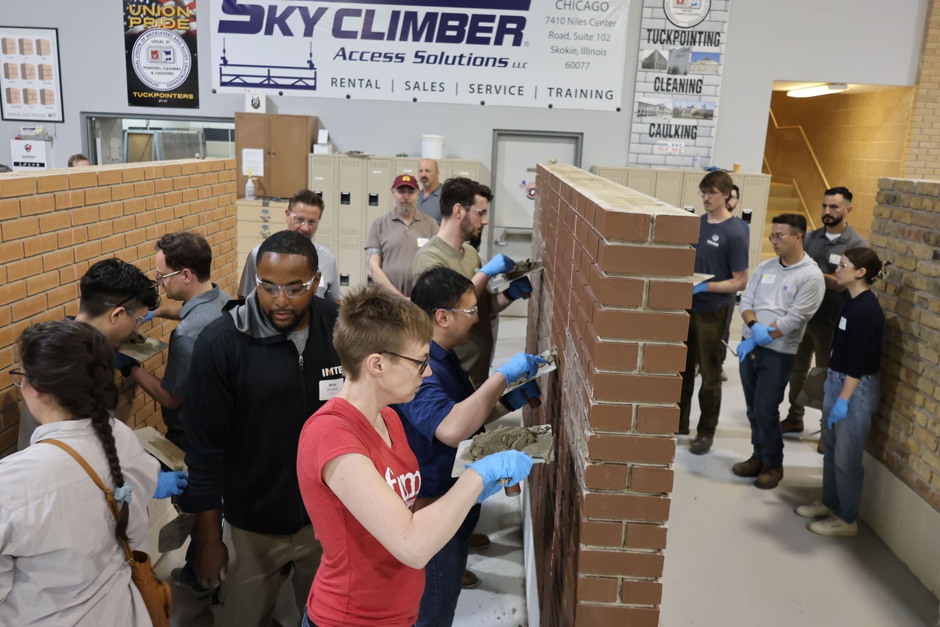
Station 2: Mortar Extraction, Preparation & Pointing — Mortar Is the Sacrificial System
In a properly functioning masonry wall, mortar is designed to fail before the masonry units. When it doesn’t, the wall starts to fail instead.
It acts as a sacrificial and breathable component, accommodating movement, allowing moisture to escape, and being replaced without damaging the surrounding units.
At this station, the focus was on how that system breaks down in the field, and why repointing is one of the most common sources of long-term failure.
Why Mortar Deteriorates, and Why Full Extraction Matters
Mortar joints deteriorate due to:
- Water infiltration and prolonged saturation
- Freeze-thaw cycling causing expansion and microfracturing
- Natural weathering over time
When deteriorated mortar is left in place (or only partially removed), it compromises the bond of the new mortar and allows moisture to remain within the joint.
One of the most common field issues is incomplete removal, particularly at the top and bottom of joints (“half moons”). These remnants limit depth and prevent proper consolidation of new mortar.
Proper extraction requires:
- Removal to a depth of approximately 2–2.5 times the joint width
- Clean, continuous joint surfaces free of debris and loose material
Without full-depth extraction, repointing becomes a surface repair, not a system correction.
Extraction Methods and Control
Two primary approaches were demonstrated:
- Mechanical extraction (grinder with sandwich blade)
- Increases production speed
- Requires precise control to avoid damaging adjacent masonry units
- Must include dust collection to comply with silica exposure standards
- Hand tooling
- Used in sensitive areas requiring greater precision
- Starting with head joints reduces stress on surrounding units
- Smaller tools provide better control and reduce edge damage
The method matters less than the outcome: clean, consistent joint geometry without damage to the masonry units.
Joint Preparation: Bond and Moisture Control
Once extraction is complete, joint preparation directly affects performance.
Two steps are critical:
- Cleaning — removal of dust and debris to ensure proper bond
- Pre-wetting — controlling substrate suction and preventing premature drying
Without pre-wetting, especially in hot or windy conditions, masonry units draw moisture out of the mortar too quickly. This results in poor curing, reduced bond strength, and early failure.
Mortar Selection: Compatibility Over Strength
Mortar selection is one of the most misunderstood aspects of restoration.
The goal is not to use the strongest material. It is to use one that behaves like the original system.
Key considerations include:
- Compressive strength relative to the masonry units
- Permeability and vapor transmission
- Ability to accommodate movement
In many historic applications, lime-based or lime-rich mortars are used because they allow the wall to “breathe” and respond to environmental changes without cracking.
When mortar is too dense or too strong, stress and moisture are forced into the masonry units instead. That leads to:
- Cracking through brick or stone rather than joints
- Spalling and face deterioration
- Trapped moisture within the wall assembly
Material behavior, not just appearance, determines long-term performance.
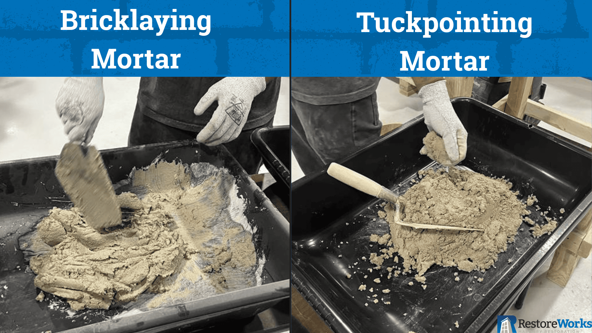
Pointing Technique and Installation
Mortar installation is not a single-step process.
Proper pointing requires:
- Placement in lifts (typically ~1/4" per pass) to ensure full consolidation
- Elimination of voids or air pockets
- Consistent packing against joint surfaces
As mortar cures, it reaches a stage known as “thumbprint hard", firm enough to hold shape, but still workable. This is the ideal point for final tooling.
Joint Profile and Water Shedding
Joint profile directly affects how water interacts with the façade.
- Concave joints
- Provide better compaction
- Shed water more effectively
- Flush joints
- Retain more surface moisture and behave differently under exposure
These are not aesthetic decisions, they directly influence durability and long-term performance.
Where Mortar Repairs Fail in the Field
Common failure conditions include:
- Shallow or inconsistent extraction
- Residual “half moons” limiting bond depth
- Mortar mixes that are too strong or too dense
- Lack of pre-wetting, leading to poor curing
- Improper joint tooling that allows water retention
When these issues occur, the system stops functioning as intended. Moisture is trapped, stress is transferred into the masonry units, and deterioration accelerates.
What This Station Demonstrated
This station reinforced that mortar is not a filler, it is a performance layer within the wall system.
When properly removed, selected, and installed, it protects the masonry and allows the wall to function as designed.
When treated as a cosmetic repair, it becomes one of the primary causes of failure.
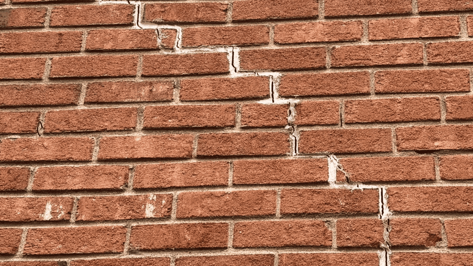
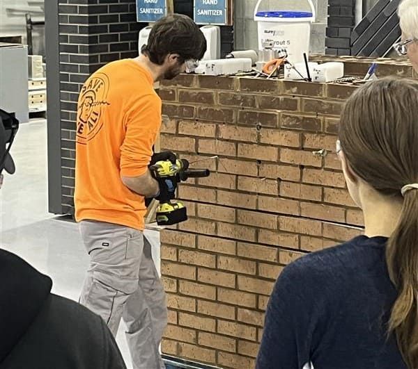
Station 3: Anchoring, Stabilization, Stitching & Beaming — Movement Requires Control, Not Concealment
All masonry structures move.
Thermal expansion, moisture cycling, settlement, and material fatigue introduce stress into the system over time. Cracking, bowing, and displacement are the visible results, but they are not the root problem. They are indicators of lost load paths, weakened connections, or ongoing movement within the assembly.
At this station, the focus was on how structural stabilization restores continuity within the wall system, without relying on full demolition or replacement.
Why Structural Stabilization Becomes Necessary
Many existing masonry buildings, particularly older or historic structures, rely on the mass and interlocking of masonry units rather than modern reinforcement.
Over time, several conditions contribute to instability:
- Water infiltration degrading embedded components
- Corrosion of steel elements (including lintels and ties)
- Differential settlement or foundation movement
- Fatigue within multi-wythe wall systems
When these conditions are not addressed, they lead to:
- Separation of wythes
- Cracking and displacement
- Loss of structural engagement between components
Left uncorrected, these issues can progress beyond performance concerns into safety risks.
Anchoring Systems: Re-Establishing Structural Continuity
Anchoring is one of the primary methods used to restore connection within a masonry system.
At this station, multiple anchor types and applications were demonstrated, including:
- Helical anchors for tying wythes together in multi-wythe construction
- Mechanical expansion and epoxy-set anchors for retrofitting masonry to structural substrates
- Corrosion-resistant materials (typically stainless steel) for long-term durability
Performance is highly dependent on:
- Proper embedment depth
- Substrate condition
- Installation accuracy
Anchors are not assumed to perform, they are verified.
Spiral Tie Installation and Pull Testing
Spiral tie installation demonstrated how localized anchoring is applied in the field, particularly in cavity wall systems or where wythes have begun to delaminate.
The process includes:
- Drilling through the exterior wythe at a prescribed angle
- Installing helical ties with grout or adhesive
- Performing pull testing to confirm bond strength and load capacity
Pull testing is critical. It provides measurable confirmation that the anchor system is functioning as intended, rather than relying on assumed performance.
Crack Stitching: Managing Tensile Forces
Crack stitching addresses stress-induced cracking by redistributing tensile forces across the affected area.
The system consists of:
- Stainless steel helical bars installed across cracks
- Embedded within bed joints using grout or epoxy
- Concealed within repointed joints to maintain façade continuity
This approach:
- Reinforces the wall without dismantling it
- Stabilizes existing cracks
- Allows controlled movement while preventing further separation
Crack stitching does not eliminate movement, it manages it.
Helical Beaming: Redistributing Loads
Helical beaming provides horizontal reinforcement in areas where load paths have been compromised.
This method uses:
- Paired helical bars installed in grout
- Forming a concealed beam within the masonry
Typical applications include:
- Reinforcing weakened wall sections
- Redistributing loads around failed or corroded lintels
- Stabilizing parapets, spandrels, and openings
This approach allows structural reinforcement without removing large portions of the wall.
Where Stabilization Work Fails in the Field
Common failure conditions include:
- Incorrect anchor selection for the substrate or load condition
- Insufficient embedment depth
- Lack of pull testing or performance verification
- Treating cracks as surface issues instead of structural indicators
- Installing reinforcement without addressing underlying causes (water, corrosion, or movement)
When stabilization is applied without diagnosing the root issue, it becomes a temporary measure rather than a long-term solution.
What This Station Demonstrated
This station reinforced that cracking and displacement are not cosmetic conditions, they are symptoms of system failure.
Anchoring, stitching, and reinforcement methods are tools to restore structural performance, but they only work when aligned with the actual cause of movement.
Stabilization is not about hiding damage. It is about re-establishing how the wall carries load and responds to stress.
Station 4: Masonry Patching & Dutchman Repair — Compatibility Determines Performance
Localized masonry repairs are often approached as visual fixes.
In reality, they are material compatibility problems within a larger system.
At this station, the focus was on how patching and unit replacement behave over time, and why repairs that look correct on day one often fail prematurely.
Why These Repairs Fail (Even When They Look Right)
Masonry materials vary significantly in:
- Porosity
- Water absorption
- Compressive strength
- Thermal movement characteristics
When repair materials don’t align with these properties, they disrupt how the wall manages moisture and stress.
The result is predictable:
- Moisture becomes trapped
- Drying is restricted
- Differential movement develops
- The repair begins to break down at the interface
A successful repair must do more than match appearance, it must behave like the original material within the system.
Patching: Material Behavior and Field Application
When original units cannot be salvaged, patching is often used to restore profile and continuity.
At this station, patching focused on both constructability and performance:
- Materials must be workable enough to allow shaping and detailing after placement
- Repairs are built in stages, then sculpted to match the original profile
- Final appearance is achieved through layered coatings, not a single application
However, performance depends on compatibility:
- Patch materials must allow vapor transmission (“breathability”)
- Dense or impermeable patches can trap moisture within more porous substrates
- Using mismatched materials (e.g., terra cotta patch on limestone) disrupts moisture movement
When patch materials don’t align with the substrate, the repair becomes a point of failure.
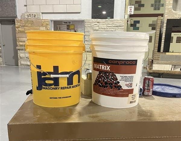
Dutchman Repairs: Partial Replacement with Structural Integration
When patching is not viable, Dutchman repair provides a more durable solution.
This method involves:
- Removing only the damaged portion of the unit
- Fabricating a replacement piece to match geometry and profile
- Mechanically anchoring the new piece into the existing unit
Performance depends on:
- Precision in cutting and fitting
- Proper anchorage to transfer load
- Alignment with the original material’s behavior
Dutchman repairs are commonly used where preserving original material is required, particularly on historic or landmark structures.
Unlike surface patching, these repairs must function structurally, not just visually.
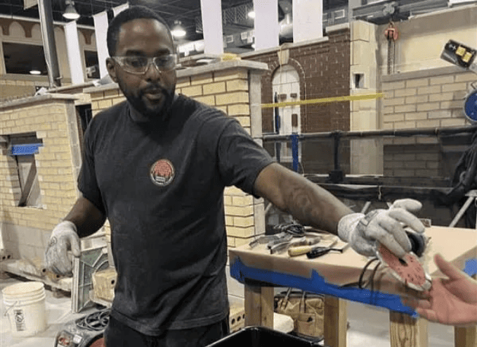
Biscuit Repairs: Speed vs. Precision Tradeoffs
Biscuit repairs were also demonstrated as an alternative method.
This approach:
- Uses a double-blade grinder to cut into the unit
- Allows for easier alignment and installation
- Requires less precision than traditional drilling or pinning methods
From a project standpoint, biscuit repairs can:
- Reduce installation time and cost
- Improve constructability in repetitive conditions
However, they introduce tradeoffs in:
- Long-term durability
- Structural engagement
- Precision of fit
They are best suited for conditions where performance demands are lower or where visual blending can compensate.
Matching and Finishing: Performance Beyond Appearance
A consistent message throughout the station was that matching is not just visual, it is functional.
Effective repairs require:
- Accurate base color matching
- Layered coatings to replicate natural variation and aging
- Finishes that align with the substrate’s porosity and moisture behavior
Coatings are not purely aesthetic. If they restrict vapor transmission or alter surface behavior, they can contribute to long-term failure.
A useful QA/QC method demonstrated at the workshop was leaving a “cut corner” in mock-ups, allowing teams to verify both the underlying repair and the final finish.
Where Localized Repairs Fail in the Field
Common failure conditions include:
- Using patch materials that are too dense or incompatible with the substrate
- Prioritizing visual match over material behavior
- Applying coatings that restrict drying
- Poor integration between repair and existing material
- Treating localized damage without addressing underlying moisture or structural issues
When these conditions exist, repairs often fail at the interface, regardless of how well they initially match.
What This Station Demonstrated
This station reinforced that patching and unit repair are not cosmetic scopes, they are extensions of the wall system.
Successful repairs require:
- Material compatibility
- Proper moisture behavior
- Integration with structural and environmental conditions
A repair that only matches visually is incomplete.
A repair that matches both appearance and performance becomes part of the system, and lasts.
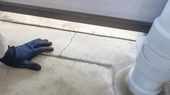
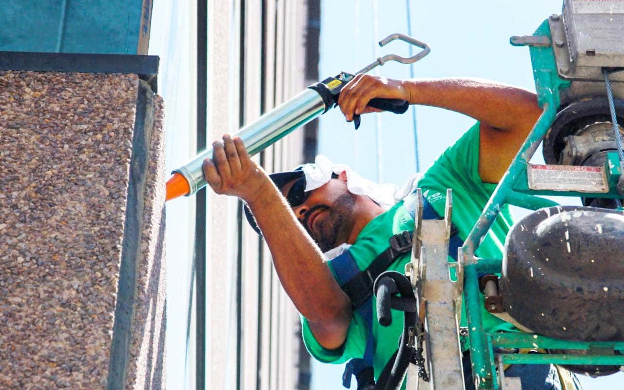
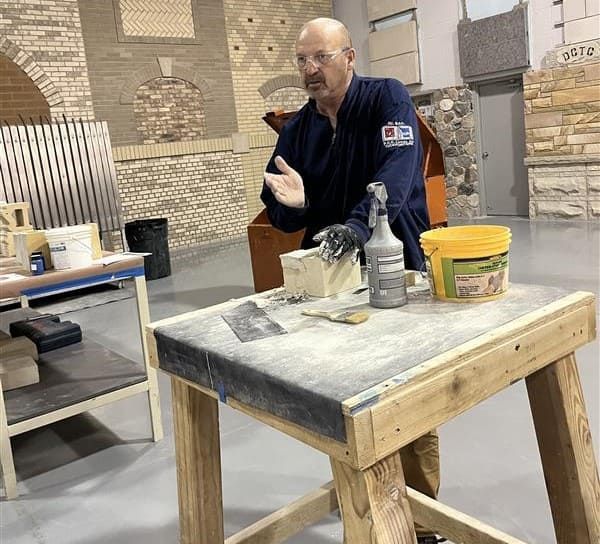
Station 5: Sealants & Joint Design — Movement Must Be Accommodated, Not Restricted
Sealants are not finishes, they are movement joints within the building envelope.
They are responsible for absorbing expansion, contraction, and differential movement between materials. When they fail, the system loses its ability to manage both movement and water.
At this station, the focus was on why sealant performance is driven less by product selection, and more by joint design, surface preparation, and installation.
Why Sealant Systems Fail
Sealant failure is rarely caused by the material itself.
It is typically the result of:
- Improper joint design
- Inadequate surface preparation
- Incorrect installation techniques
- Incompatible materials
When these conditions exist, adhesion fails, movement is restricted, and the joint begins to break down.
This leads to:
- Water infiltration at transitions and penetrations
- Loss of air and moisture control within the wall assembly
- Accelerated deterioration of adjacent materials
Sealants do not fail randomly, they fail at predictable weak points in the system.
Sealant Selection: Performance Criteria
A high-performing sealant must be selected based on how the joint is expected to behave, not just the substrate.
Key considerations include:
- Movement capability (anticipated expansion and contraction)
- Adhesion to adjacent materials
- Durability under UV exposure, temperature cycling, and environmental conditions
- Compatibility with surrounding materials and coatings
There is no one-size-fits-all solution. The wrong sealant in the right joint will still fail.
Backer Rod and Joint Design
Backer rod is not filler, it controls how the sealant performs.
Its purpose is to:
- Establish proper joint depth
- Create a bond breaker at the back of the joint
- Prevent three-sided adhesion
Three-sided adhesion restricts movement and concentrates stress within the sealant, leading to premature failure.
Materials demonstrated at the station included:
- Open cell (larger, more compressible, but moisture-absorbing)
- Closed cell (moisture-resistant, but sensitive to puncture and outgassing)
- Soft rod (compressible without outgassing)
- Bond breaker tape (used where depth is limited)
Proper selection depends on joint size, depth, and exposure conditions.
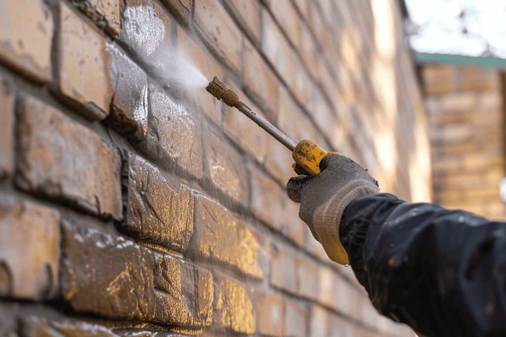
Surface Preparation and Installation
Even the best sealant will fail without proper preparation.
Critical steps include:
Mechanical Cleaning
- Removal of existing sealant and contaminants
- Grinding, brushing, or cutting to expose sound substrate
- Oil-free compressed air to remove debris
Two-Wipe Method
- First wipe with approved solvent
- Second wipe with clean cloth to remove residue
- Frequent rag changes to prevent contamination
Primer Application
- Applied only to joint sides, not the back
- Light, consistent coverage
- Installed and sealed within the same working window
Most adhesion failures trace back to breakdowns in this process, not the material itself.
Testing and Verification
Sealant performance should not be assumed, it should be tested.
At the station, pull testing was demonstrated as a simple field method to verify adhesion.
Testing is typically performed:
- At the start of a project
- When materials or substrates change
- When environmental conditions shift
This provides confirmation that the system is performing as intended before full installation proceeds.
Where Sealant Work Fails in the Field
Common failure conditions include:
- Three-sided adhesion restricting movement
- Improper backer rod selection or installation
- Inadequate surface preparation
- Use of incompatible sealants or primers
- Lack of field adhesion testing
When these issues occur, the joint loses its ability to accommodate movement, and failure becomes inevitable.
What This Station Demonstrated
This station reinforced that sealants are not cosmetic, they are functional components of the building envelope.
When properly designed and installed, they:
- Absorb movement
- Maintain watertight transitions
- Protect adjacent materials
When treated as a finish detail, they become one of the most common sources of failure in the system.
A System-First Approach to Masonry Restoration
Each station at the workshop focused on a different scope: water management, mortar performance, structural stabilization, and material compatibility.
Individually, these are often treated as separate repairs.
In practice, they are all part of the same system.
- Poor flashing leads to water retention
- Water retention accelerates mortar deterioration
- Incompatible repointing traps moisture and increases stress
- Movement develops, leading to cracking and displacement
- Structural reinforcement is introduced
- Localized repairs address visible damage, but not the underlying cause
This is how most masonry failures progress, not as isolated issues, but as a chain reaction.
Effective restoration requires a different approach.
It requires understanding how the wall functions as a system, identifying the root cause of failure, and sequencing repairs so each component supports long-term performance.
That was the objective of the workshop conducted with the International Masonry Institute, to move beyond individual repair methods and focus on how masonry systems actually behave in the field.
Because in most cases, the condition you see at the surface is only one part of what’s happening within the wall.
And unless the system is addressed, the failure will return.
This hands-on workshop brought together architects, engineers, and construction professionals to better understand how masonry systems perform in the field.